
cdi electronics troubleshooting guide
Welcome to the CDI Electronics Troubleshooting Guide, your comprehensive resource for diagnosing and resolving issues with your outboard ignition system. This guide provides practical tips, reference data, and DVA charts to ensure optimal engine performance. Let us help you!
CDI, or Capacitor Discharge Ignition, systems are a critical component in many outboard engines, responsible for generating the high-voltage spark needed for combustion. Understanding the basics of these systems is essential for effective troubleshooting and maintenance. CDI systems replaced traditional points-based ignition systems, offering improved reliability and performance.
At its core, a CDI system uses a capacitor to store an electrical charge. This charge is then rapidly discharged through an ignition coil, creating a high-voltage pulse that is sent to the spark plugs. This process is precisely timed to ensure optimal engine performance. Key components of a CDI system include the stator, which generates the initial charge; the capacitor, which stores the charge; the ignition coil, which amplifies the voltage; and the trigger, which controls the timing of the discharge.
CDI systems are known for their ability to deliver consistent spark, even at high engine speeds; However, like any electronic system, they are susceptible to failures. This guide will help you identify common problems and provide step-by-step instructions for diagnosing and resolving them. Remember that proper installation and maintenance are crucial for the longevity and performance of your CDI system. Let us begin!

Common CDI Problems
CDI systems, while robust, can experience a range of issues that affect engine performance. One of the most common problems is a complete lack of spark, which can be caused by a faulty stator, CDI unit, or ignition coil. Intermittent spark is another frequent issue, often resulting from loose connections, corroded terminals, or a failing trigger.
Rough idling is another symptom that can indicate a CDI problem. This may be due to incorrect timing, a weak spark, or a malfunctioning switch box. Decreased fuel efficiency can also be a sign of a CDI issue, as improper ignition can lead to incomplete combustion. Misfires, particularly at high RPMs, are often linked to a failing CDI unit or ignition coil.
Other common problems include issues with the stop circuit, which prevents the engine from being shut off, and kill switch malfunctions, which can prevent the engine from starting. Environmental factors, such as moisture and vibration, can also contribute to CDI failures. Regular inspection and maintenance can help prevent these issues, ensuring reliable engine performance. By addressing these common problems promptly, you can avoid more serious engine damage and maintain optimal fuel economy. Let’s keep on going!
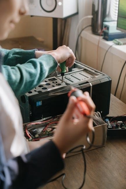
Tools for CDI Troubleshooting
Effective CDI troubleshooting requires a specific set of tools to accurately diagnose and resolve ignition system problems. A digital multimeter (DMM) is essential for measuring voltage, resistance, and continuity, helping to identify faulty components and wiring issues. A DVA (Direct Voltage Adapter) is crucial for testing peak voltage outputs, particularly from the stator and trigger coil, ensuring they meet specified values;
An inductive timing light is necessary for verifying ignition timing accuracy, which can affect engine performance and fuel efficiency. A spark tester allows you to visually confirm the presence and quality of spark at the spark plugs. A compression tester helps rule out mechanical issues that might mimic ignition problems. Additionally, a wiring diagram specific to your engine model is indispensable for tracing circuits and identifying correct connections.
Specialized tools like a CDI tester can provide more detailed analysis of the CDI unit’s performance, but a DMM and DVA are often sufficient for most troubleshooting tasks. Don’t forget basic tools such as screwdrivers, pliers, and wire strippers are also necessary for accessing and manipulating electrical components. Having these tools on hand enables you to systematically diagnose and repair CDI-related issues, ensuring reliable engine operation and extending the lifespan of your marine equipment. Let’s get to work!
No Spark Troubleshooting

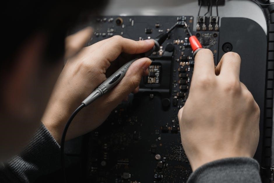
When troubleshooting a no-spark condition in a CDI system, systematically check each component to pinpoint the fault. Begin by verifying the kill switch circuit, disconnecting the kill wire to eliminate potential shorts. Inspect the spark plugs for damage or fouling, and ensure they are properly gapped. Use a spark tester to confirm spark presence at the plugs.
Next, test the stator and trigger coil with a digital multimeter, comparing resistance values to the manufacturer’s specifications. A Direct Voltage Adapter (DVA) can measure peak voltage output from these components under load, providing more accurate readings. Examine the CDI unit itself for any signs of physical damage or corrosion. Check all wiring connections for looseness, corrosion, or breaks, ensuring good continuity.

If the stator or trigger coil tests faulty, replacement is necessary. If wiring is suspect, repair or replace damaged sections. If the CDI unit is the problem, consider replacing it with a new one. Finally, always consult the engine’s service manual for specific troubleshooting steps and component values. By following this structured approach, you can efficiently diagnose and resolve no-spark issues, restoring reliable ignition to your engine and getting you back on the water quickly. Let’s start checking!
Troubleshooting Intermittent Spark
Diagnosing intermittent spark issues in a CDI system requires meticulous attention to detail, as the problem may not be consistently present. Start by carefully inspecting all wiring connections for looseness, corrosion, or chafing. Pay close attention to the connectors at the CDI unit, stator, trigger coil, and ignition coils. Vibration can cause intermittent connections, so gently wiggle wires while monitoring for spark.
Check the stator and trigger coil for heat-related failures. These components may function when cold but fail as they warm up. Use a multimeter to monitor resistance as the engine runs, noting any fluctuations. A DVA adapter can help detect voltage drops under load, revealing weak components.
Examine the spark plugs and wires for damage or excessive resistance. A cracked spark plug insulator or a corroded wire can cause intermittent spark. Try replacing the plugs and wires with known good ones to eliminate them as potential causes. Also, consider external factors. Fuel delivery problems can mimic ignition issues, so ensure adequate fuel flow and proper carburetor function. Finally, review the engine’s service manual for specific troubleshooting tips and component specifications. By systematically addressing these potential problem areas, you can effectively pinpoint and resolve intermittent spark issues.
Troubleshooting Rough Idling
Rough idling in an engine with a CDI ignition system can stem from various issues, requiring a systematic approach to diagnose; Begin by ensuring the engine is receiving adequate and consistent fuel supply. Check the fuel filter, fuel pump, and carburetor or fuel injectors for clogs, leaks, or malfunctions. A lean fuel mixture can cause erratic idling. Next, examine the ignition components, including spark plugs, wires, and coils, for wear or damage. Replace any faulty parts to ensure proper spark delivery.

Inspect the CDI unit itself for signs of damage or corrosion. Use a multimeter to test the voltage output from the CDI unit to the ignition coils, comparing it to the manufacturer’s specifications. A weak or inconsistent signal can cause misfires and rough idling. Additionally, check the engine’s timing and synchronization. Incorrect timing can lead to poor combustion and unstable idling.
Also, rule out vacuum leaks, which can disrupt the air-fuel mixture and cause rough idling. Inspect vacuum hoses and intake manifold gaskets for cracks or leaks. Finally, consider mechanical issues. Low compression, worn piston rings, or valve problems can all contribute to rough idling. By systematically checking these areas, you can identify the root cause and restore smooth idling.
Troubleshooting Decreased Fuel Efficiency
Decreased fuel efficiency in an engine equipped with a CDI ignition system can indicate several underlying problems. Begin by inspecting the spark plugs. Worn, fouled, or incorrectly gapped spark plugs can lead to incomplete combustion, wasting fuel. Replace them with the recommended type and ensure they are properly gapped. Next, check the air filter. A dirty or clogged air filter restricts airflow, causing a richer fuel mixture and reduced efficiency. Clean or replace the air filter as needed.
Examine the fuel system components, including the fuel filter, fuel pump, and fuel injectors or carburetor. A clogged fuel filter restricts fuel flow, while a malfunctioning fuel pump may not deliver adequate pressure. Dirty or worn fuel injectors or a poorly adjusted carburetor can disrupt the air-fuel mixture, leading to inefficient combustion. Clean or replace these components as necessary.

Also, consider issues with the CDI unit itself. A faulty CDI unit may not be delivering the correct timing or voltage to the ignition coils, resulting in poor combustion. Use a DVA adapter to test the CDI unit’s output and compare it to the manufacturer’s specifications. Finally, check for vacuum leaks, which can disrupt the air-fuel mixture and reduce fuel efficiency. By addressing these potential issues, you can restore optimal fuel efficiency.
Using a DVA Adapter

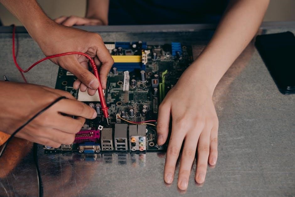
A DVA (peak-reading Voltmeter Adapter) is an invaluable tool for troubleshooting CDI (Capacitor Discharge Ignition) systems. It allows you to measure peak voltage outputs, which are crucial for diagnosing issues within the ignition system. To begin, ensure your digital multimeter (DMM) is compatible with the DVA adapter; shielded DMMs are typically required to minimize interference.
Connect the DVA adapter to your DMM, following the manufacturer’s instructions. Typically, this involves plugging the DVA adapter into the DMM’s voltage input and grounding it appropriately. Next, identify the specific test points on the CDI system you need to measure, such as the stator output, trigger coil output, and CDI output to the ignition coil.
With the engine running or cranking (depending on the test), carefully probe the test points with the DVA adapter. The DMM will display the peak voltage readings. Compare these readings to the manufacturer’s specifications for your specific engine model. Significantly lower or absent voltage readings indicate a potential problem with the component being tested. For example, a low stator output suggests a faulty stator, while a weak trigger signal could point to a failing trigger coil. Using a DVA adapter provides accurate and reliable voltage measurements, enabling precise CDI system diagnostics.
Stop Circuit Troubleshooting
The stop circuit, also known as the kill circuit, is designed to safely shut down your engine. Issues within this circuit can prevent the engine from starting or cause it to stall unexpectedly. Begin by visually inspecting all wiring connections related to the stop circuit, including the key switch, shift switch (if equipped), harness connections, and the power pack itself. Look for any signs of corrosion, damage, or loose connections.
Next, disconnect the kill wire(s) from the power pack. If the engine now starts, the fault lies within the stop circuit itself. Use a multimeter to check for DC voltage on the kill wire(s) with the ignition switch in the “on” and “off” positions. There should be no voltage when the switch is “off” and a specific voltage (usually battery voltage) when the switch is “on”.
If voltage is present when the switch is “off,” a faulty key switch, harness, or shift switch is likely the culprit; Disconnect each component one at a time to isolate the issue. If disconnecting the shift switch resolves the problem, it needs replacement. Similarly, test the key switch by disconnecting it and checking for continuity. A proper key switch should have continuity only when in the “on” position. By systematically testing each component, you can effectively troubleshoot and repair the stop circuit.
Kill Switch Troubleshooting
The kill switch is a critical safety feature designed to immediately stop the engine in emergency situations. If your kill switch is malfunctioning, it could prevent the engine from starting or cause it to cut out unexpectedly. Start by visually inspecting the kill switch and its wiring for any signs of damage, corrosion, or loose connections. Ensure the switch moves freely and isn’t sticking in either the “on” or “off” position.
To test the kill switch, disconnect it from the ignition system. Use a multimeter to check for continuity across the switch terminals in both the “on” and “off” positions. In the “on” position, there should be no continuity, indicating an open circuit. In the “off” position, there should be continuity, indicating a closed circuit that grounds the ignition system and stops the engine.
If the kill switch fails either of these tests, it needs replacement. Also, inspect the wiring harness connected to the kill switch for any shorts or breaks. A faulty wiring harness can mimic the symptoms of a bad kill switch. By carefully testing the switch and its associated wiring, you can effectively diagnose and resolve kill switch issues, ensuring your engine’s safety system functions correctly.
CDI Remapping and Performance Tuning
CDI remapping and performance tuning involve modifying the ignition timing and fuel delivery settings within the CDI unit to optimize engine performance. This process can enhance horsepower, torque, and throttle response, leading to a more exhilarating driving or boating experience. However, it’s crucial to approach CDI remapping with caution and expertise, as incorrect adjustments can lead to engine damage.
Before considering CDI remapping, ensure your engine is in excellent mechanical condition. Address any existing issues such as worn spark plugs, clogged fuel injectors, or vacuum leaks. These problems can mask the true potential of remapping and may even worsen with increased engine stress.
The remapping process typically involves using specialized software and a diagnostic interface to communicate with the CDI unit. The software allows you to adjust parameters such as ignition timing advance, fuel mixture ratios, and rev limits. It’s recommended to start with conservative adjustments and gradually increase them while monitoring engine performance and vital signs. Keep a close eye on parameters like exhaust gas temperature (EGT) and air-fuel ratio (AFR) to prevent overheating or lean conditions.